Using IGBT Based Electronic Device Static VAr Generators (SVG)
What is Power Factor?
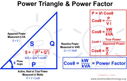
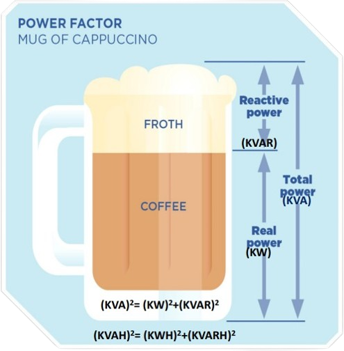
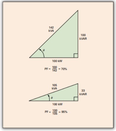
Power Factor is the ratio of real power (KW) to apparent power (KVA) in an electrical system, indicating efficiency. CR Energy offers services involving calculations for KVA, KW, and KVAR, using formulas like (KVA)^2 = (KW)^2 + (KVAR)^2 and (KVAH)^2 = (KWH)^2 + (KVARH)^2 to optimize energy usage.
Advantages of Industrial Power Factor Correction Services
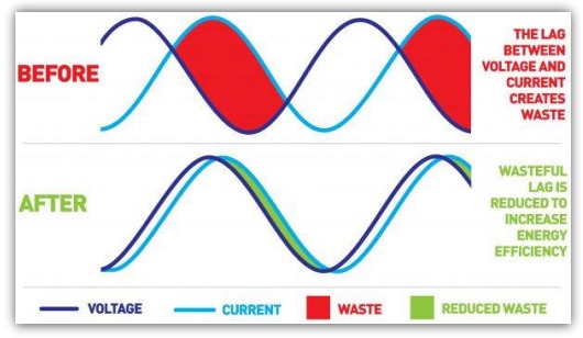
Advantages of Industrial Power Factor Correction Services include reduced energy costs, extended equipment lifespan, improved power quality, and increased operational efficiency. These benefits enhance overall performance and reliability in industrial operations.
Reduced Energy Costs
Lower electricity bills by improving power factor and reducing reactive power demand.
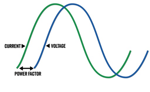
Power factor is the relation between the kW and the kVA drawn by an electrical load where the kW is the actual load power and the kVA is the apparent load power.
Role of MV Transformer in Displacement Power Factor
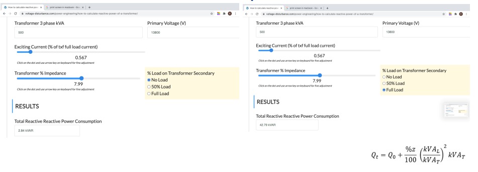
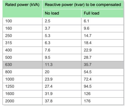
Reactive Power of Transformer depends on following
Reactive power consumed by shunt magnetizing reactance of transformer (no load condition)
Transformer percentage short circuit impedance
Load kVA ( % of Transformer rated kVA)
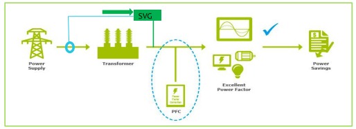
SVG compensates dynamic reactive power of transformer with load change
The reactive power drawn by power transformer could be as high as 5% of the transformer rating when supplying full load current. Power factor at the primary of the transformer is usually lower than what is measured at the secondary due to this reactive power requirement of transformer.
With SVG No need to replace aged transformer or high Impedance Transformer
SVG can compensate high reactive power of aged
Transformer – Sensing being on MV/HV Side
SVG can compensate extremely high reactive power of High Impedance Transformer – Sensing being on MV/HV Side
SVG Improves Power factor of Transformer at No Load
During no load condition of transformer, the excitation or magnetizing current flow in the primary winding of the transformer. This excitation current is made up of large component of magnetizing component of current (Im) which is in quadrature with the applied voltage and comparatively small in phase component of current (Ie) which is in phase with the applied voltage. Thus due to large magnetizing component, power factor of the transformer will be very low. Power factor will be usually 0.1 to 0.2 lag
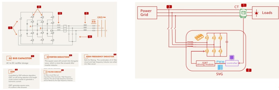
Internal Design & Structure of SVG
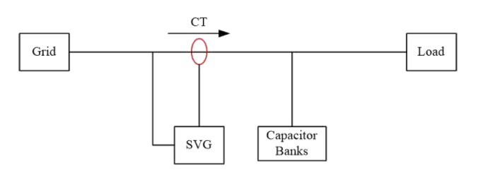
Load current is detected through external CTs and fed to the internal Controller where an Instantaneous Reactive Power algorithm separates the active power from the reactive power. A compensating reactive power requirement is dynamically and accurately calculated and sent to the IGBT control where a PWM signal is generated at a switching frequency of 20kHz. A compensating capacitive reactive power or inductive reactive power is controlled by the manipulation of the DC bus voltage in comparison to the AC line voltage. Thus a capacitive current or inductive current will flow, creating a reactive power exchange with the network voltage level
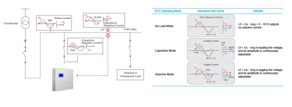
Working Principle of SVG
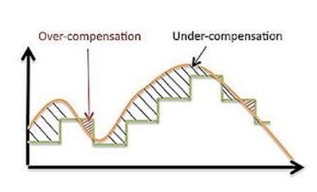
SVG Generates exact reactive power (Step less Response)
It operates by detecting the load current on a real-time basis through external CT’s and determining the reactive content of the load current. The data is analysed and the SVG’s controller drives the internal IGBT’s by using pulse width modulation signals to make the inverter produce the exact reverse reactive current of the corresponding load reactive content. This is injected to the grid to compensate the reactive content of the load current . By adjusting the output voltage amplitude and phase angle or by directly controlling the AC side current, the SVG can absorb or generate var according to the load reactive power or the grid
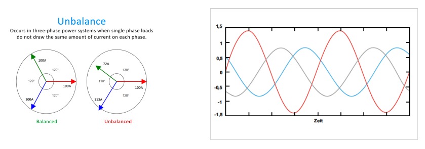
SVG Senses & Compensates Phase wise Reactive Power
A traditional switched capacitor type PFC system measures one phase and then provides stepped kVAr compensation to all phases based on the measurements taken from the one phase being measured. The other two phases all receive the same compensation, irrespective of what the other two phases actually need. The SVG measures all 3 phases and provides specific dynamic kVAr compensation each phase.
SVG can operate efficiently up to 12 % THDv & APFC resonates &
amplify Harmonics
SVG Collaborates with existing APFC Panel
No Need to remove or replace existing APFC Panel
APFC is responsible for course reactive compensation
SVG manages fine reactive compensation
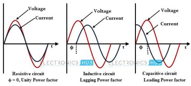
SVG corrects both inductive & Capacitive Reactive Power -Bidirectional
A load that has a lagging power factor is, by convention, said to be receiving reactive power from the source. A load that has a leading power factor is, by convention, said to be delivering reactive power to the source. … Therefore, lagging reactive power is positive and leading reactive power is negative. SVG Compensates both inductive and capacitive loads
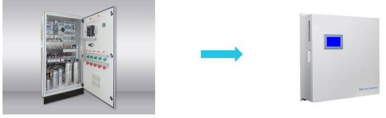
SVG is Virtually Maintenance free & Far Safer
100% solid state with latest generation IGBTs
Electronics free from contaminated air flow
Long life cooling fans are simple to replace
Capacitor free. No Need for constantly checking capacitors for degradation or failure
Low risk – no swollen or leaking capacitors. Reduced fire risk
No contactors to replace
Design service life of more than 100,000 hrs, without maintenance. That’s more than 10 years operation in a plant that operates 24/7. Capacitor based systems can last as little as three years
High power density means less precious switchboard room is use
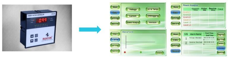
With SVG possible to monitor all parameters/graphs/SCADA/Wi fi
Displays Phase Wise Voltage, Current, Apparent Power, Active Power, Reactive Power, Power Factor
Displays Wave form & Spectrum of Phase Wise Voltage, Current
Displays THDv & THDi Load side & Grid Side
Displays Phase wise compensation
Displays temperature of all critical junctions of SVG
Provides data on RS485
Provides data on Wi fi
Display Alarms & History
Displays data on Mobile or SCADA
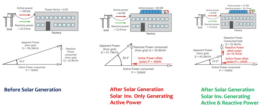
SVG Provides extra reactive power required after addition of Solar Power Plant
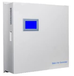
SVG standard Module rating & Mechanical Dimensions
SVG Module Standard Rating
30 KVAR – 500 x 191 x 585 - 36 Kg
50 KVAR – 500 x 191 x 585 - 36 Kg
100 KVAR – 500 x 286 x 557 - 48 Kg
Any ratings can be achieved by paralleling modules of same or different ratings
Mounting can be Rack mounting or Wall Mounting
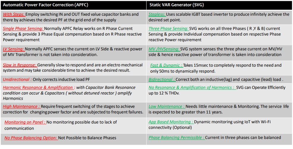
Comparison
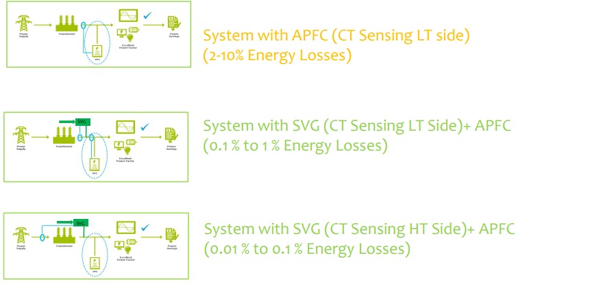
SVG has capability to connect the sensing in MV/HV
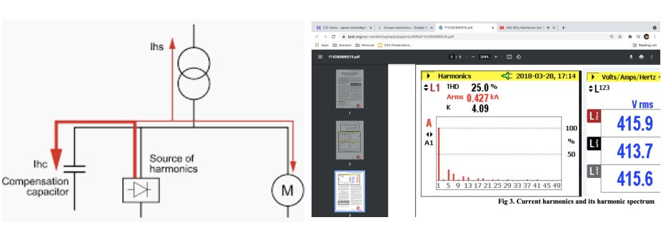
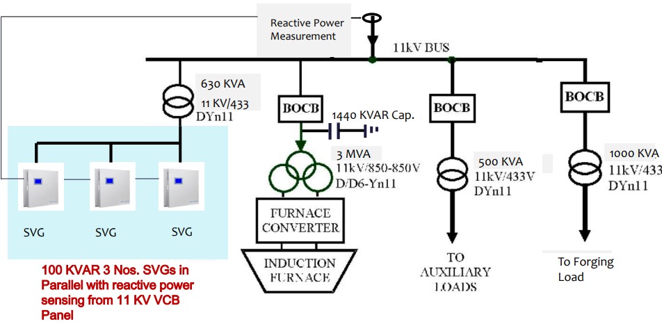
SVG Configuration for a Furnace with very High Harmonics Level
Details of SVG System Installed at GMK Steel, Ghaziabad (Our Biggest Installation)
Details of GMK Steel
Voltage Level = 11 KV
Connected Load = 2850 KVA
Furnace Transformer Rating = 3000 KVA
Auxiliary Transformer Rating = 500 KVA
SVG Transformer Rating = 630 KVA
Forging Transformer Rating = 1000 KVA
HT Capacitor Installed = 1440 KVAR
Voltage Harmonics Level up to 5 % (THDv)
Current Harmonics Level up to 70 % (THDi)
Power Factor before SVG Installation : 0.94
Rating of SVG Installed = 300 KVAR
Power Factor achieving after SVG Installation = 0.985
Average Monthly Electricity Bill = 30 Lacs
Saving due to power factor improvement = 1,35,000
Overall Investment = 12.00 Lacs
ROI of SVG System = 8.88 Months
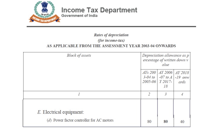
Accelerated Tax Depreciation @ 40 % per year on Installation of SVG
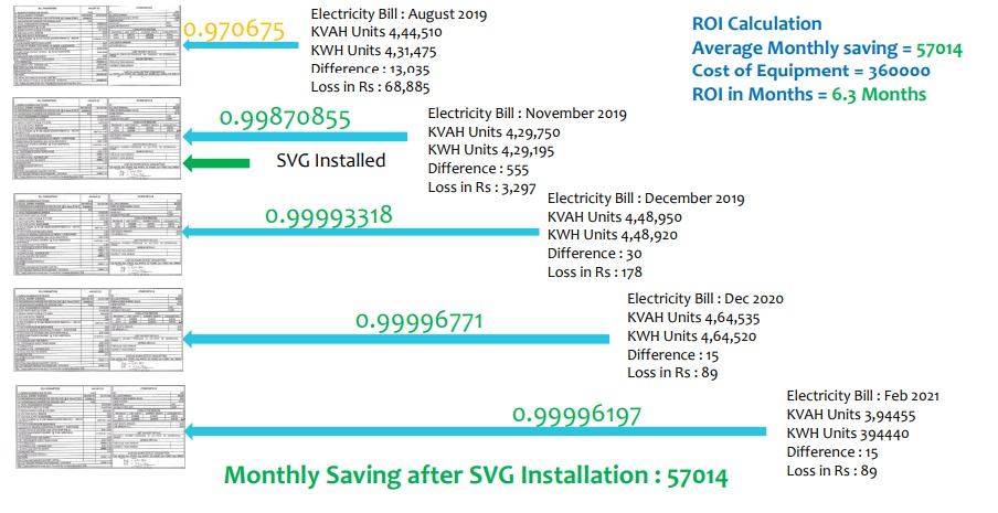
Reference Example ( LT Sensing )Saving Achieved in HaridwarPlant thru SVG
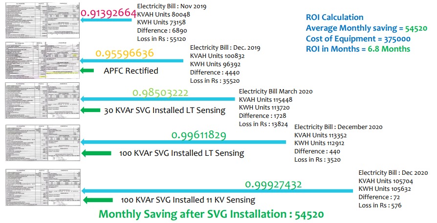
Reference Example ( 11 KV Sensing )Saving Achieved in FaridabadPlant thru SVG
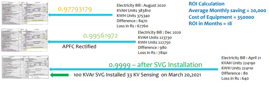
Reference Example ( 33 KV Sensing )Saving Achieved in NoidaPlant thru SVG
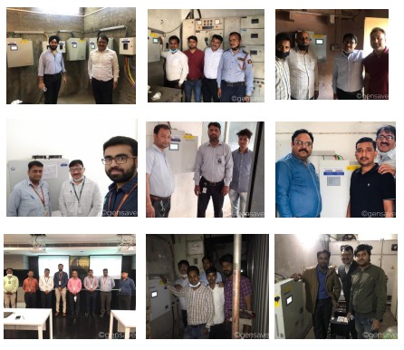
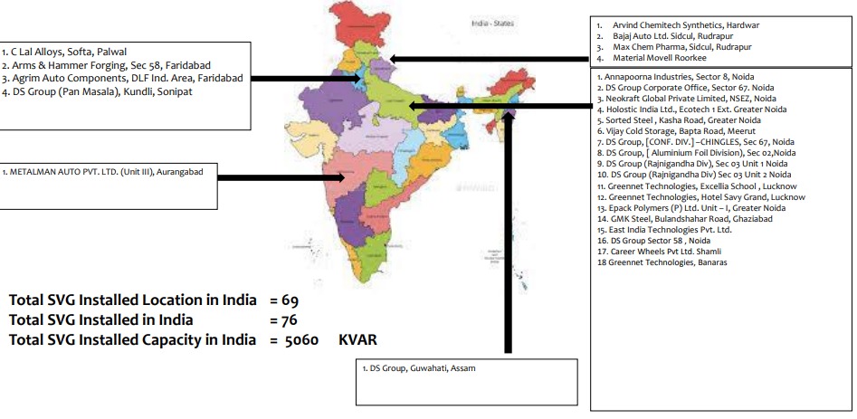
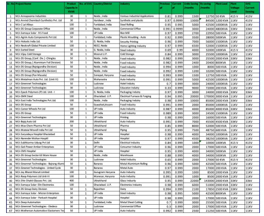
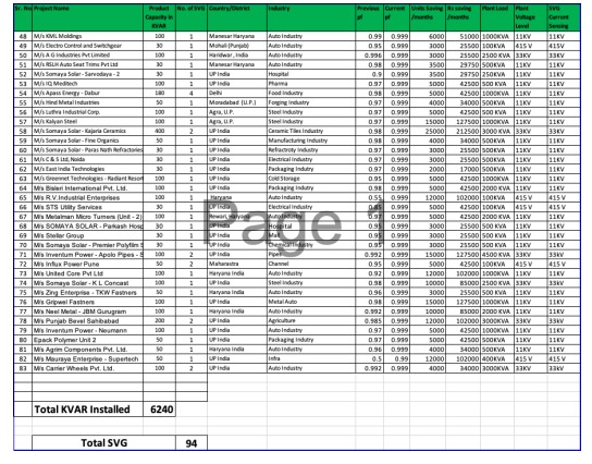
Our Installed Base in India
Gensave Installed Base
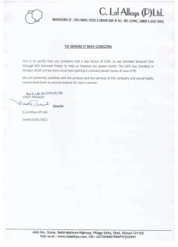
Appreciation Letters
Customer who believed in Gensave & it’s innovative solutions